Definition/Introduction
The lensmaker equation is a mathematical computation to determine the focal length of a lens in air. The focal length of a lens is defined as the distance from the center of the lens to an optical point to which all light rays are refracted.[1]
The lensmaker equation quantifies the relationship between the focal length, refractive index, thickness, and curvature of a lens and is used to produce a lens with a desired focal point; this is the ideal lens for a given refraction.[2]
The lensmaker equation may be used to design simple lenses, double-convex or double-concave, meniscus, and plano-convex or plano-concave lenses. The lensmaker equation also has utility in determining the optical power of intraocular lenses placed after cataract surgery.[3][4]
Issues of Concern
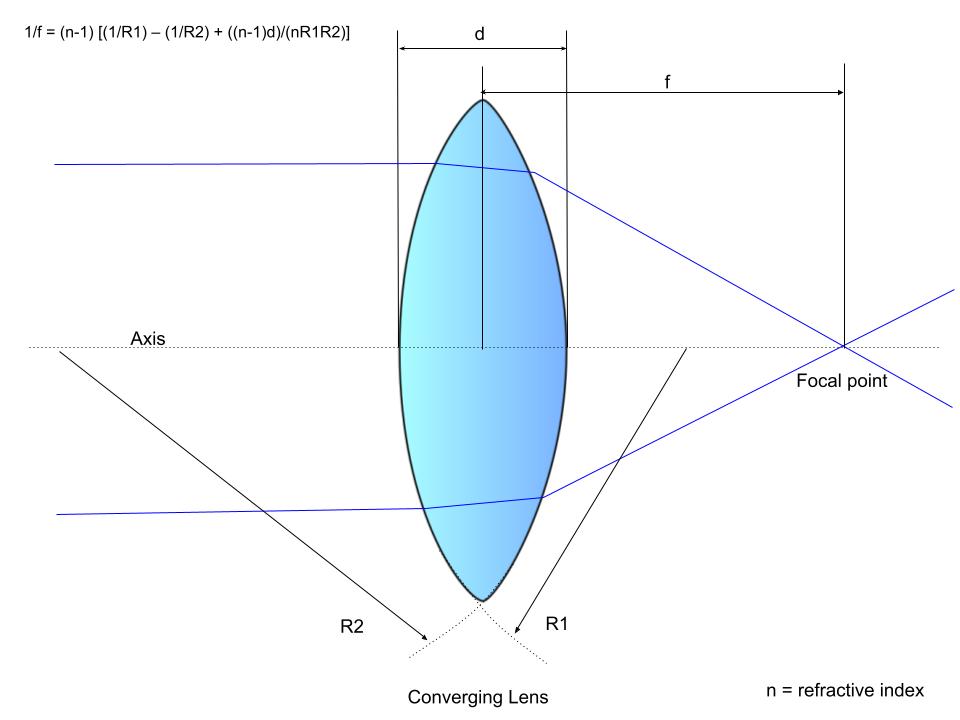
The lensmaker equation is given by:
Equation 1. Lensmaker Equation
1/f = (n-1) ⋅ [(1/R1) – (1/R2) + {[(n-1)d]/(n⋅R1⋅R2)}], where
f: Lens focal length
n: Lens material refractive index
R1: Radius of curvature of the lens surface closest to the light source
R2: Radius of curvature of the lens surface furthest from the light source
d: Lens thickness
This is a fundamental equation in lens production, utilizing the refractive index, radii of curvature, and thickness of lenses to produce a lens with a targeted focal point based on the desired refraction.[3] The reciprocal of the focal length of the lens, 1/f, is equivalent to the optical power measured in diopters.
Sign Convention
The sign of a lens signifies an important property of the surface of the radii of curvature of the lens. Sign convention dictates that a positive radius, R, occurs when the center of curvature is further along in the path of the light ray, and a negative radius, R, occurs when the rays have already passed by the center of the surface of curvature. Convex lenses, which converge light in a positive lens, have an R1 >0 and R2 <0. Conversely, concave lenses have R1 <0 and R2 >0. By convention, lenses that converge are assigned a positive sign, and lenses that diverge are assigned a negative sign.[1]
Thin Lens Approximation
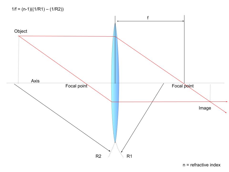
Thin lenses can be defined as lenses whose thickness, t, is significantly less than the radii of curvature of its surfaces. The thin lens approximation assumes that light rays are only refracted once when they pass through a lens, as would occur with a lens width of zero, rather than refracted twice, as occurs with lenses in real life.[1] While most lenses have a nonnegligible thickness and are thus thick lenses, this assumption is helpful as it removes the phenomenon of “spherical aberration.”[1][5] The use of the thin lens approximation allows the lensmaker equation to be simplified to:
Equation 2. Thin Lens Approximation
1/f = (n-1) ⋅ [(1/R1) – (1/R2)]
Thus, the simplified equation suggests that light travels in a straight line through the center of a thin lens because the light is refracted equally upon exiting the lens as it does when it enters.[1] One limitation of this simplification is that by assuming a thin lens model for the cornea and lens, the true physiological estimate of the power of the cornea and lens is not accurately described.[4] Also, spherical aberrations of the cornea, which lead to astigmatism, are not accounted for in the simplified lensmaker formula.
Lens in a Medium Other Than Air
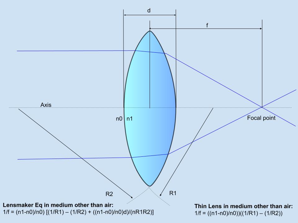
A lens placed inside a medium with a refractive index that does not approach 1, as air does, will have a different refractive power that can be calculated using a modified lensmaker equation. In these cases, the index of refraction (n1) and the index of refraction of the medium (n0) replace the (n-1) component of the lensmaker equation and the thin lens approximation with [(n1-n0)/n0]. In essence, increasing the index of refraction of the medium relative to the index of refraction of the lens will reduce the [(n1-n0)/n0] portion of the lensmaker equation and thus reduce the refracting power of the lens.
Convex Lens Model
Using the thin lens model, it can be assumed that rays of light travel in a straight line through the center of the thin lens. Other rays travel parallel to the optical axis as collimated rays to a focal point on the opposite end of the lens.[1] Furthermore, other rays travel as collimated rays parallel to the optical axis on the same side of the lens. Ultimately, convex lenses refract all collimated rays to converge at the focal point on the opposite side of the lens relative to the light source.[1]
Concave Lens Model
For concave lenses, rays of light once again pass straight through the center of the lens using the thin lens assumption. Other rays begin as collimated rays, travel parallel to the optical axis, and are refracted so that their imaginary continuation passes through the focal point on the opposite side of the lens. The same occurs for rays on the same side of the lens.[1] This occurs because concave lenses diverge light rays so that the imaginary continuations of the light rays converge at the focal point on the same side of the lens as the light source. [1] This convergence of imaginary continuations is manifested as virtual images only seen when looking through the lenses.
Magnification and Aniseikonia
Altering the optical power and, thus, the focal point of a lens with the lensmaker formula can impact the magnification of resultant images when looking through the lens. Differences in spectacle magnification between the right and left lens can be used to calculate a phenomenon called optical aniseikonia.[5] Aniseikonia is characterized by a difference in the perceived shape or size of the image and is a cause of amblyopia.[5] Optical aniseikonia is caused by anisometropia, and retinal aniseikonia is caused by disturbances to the retina.[5][6] Iseikonic spectacle lenses are used to manage aniseikonia by altering the vertex distance, base curve, center thickness, and index of refraction of spectacle lens material to provide differing magnification of one lens compared to the other.[5]
The magnification produced by iseikonic lenses is given by:
Equation 3. Magnification
Mt = Ms x Mp, where
Mt: magnification
Ms: lens shape factor determined by 1/{[1-(t⋅D1)]/n}
Mp: lens power factor determined by 1/[1-(h⋅Dv)], and
n: refractive index
D1: base curve
t: lens thickness
Dv: dioptrical power of lens
h: vertex distance in meters
Thus, magnification is impacted by altering any one of these lens variables in the creation of a lens:
- Increased refractive index (n) leads to decreased magnification and increased minification.
- Increased, or steepening, base curve (D1) causes increased magnification and decreased minification.
- Increased thickness of the lens (t) increases magnification and decreases minification.
- Increased lens power (Dv) leads to increased magnification for plus lenses and minification for minus lenses.
- Increased vertex distance (h) causes increased magnification in plus lenses and minification in minus lenses.[5]
Optical aniseikonia, caused by anisometropia, has a fixed lens power (Dv); the base curve, center of the thickness, refractive index, and vertex distance of the iseikonic lens have an important effect.[5] These lenses are incredibly useful in treating aniseikonia if the eyes differ by ≤3 diopters. At this maximum difference, the iseikonic lenses will have a visibly different base curve and thickness.[5]
Limitations
When calculating lens power using the lensmaker equation, using a constant equivalent refractive index for the human crystalline lens will result in slight errors dependent on age.[7] The human lens has a gradient refractive index that increases when moving from the outer edges toward the center, ranging from a maximum of 1.42 at the core to a minimum of 1.37 at the surface.[8][9][10][11][7][12] Thus, the common usage of a fixed refractive index for the human lens leads to the overestimation of power in old lenses and the underestimation of power in young lenses.[7] This can subsequently lead to errors in calculations of the lens thickness and radii of curvature.[7]
Clinical Significance
Spectacle Lenses
The lensmaker formula quantifies an important optical principle that lens manufacturers employ to produce different types of spectacle lenses, including double-convex or double-concave lenses, plano-convex or plano-concave lenses, and the newer meniscus lenses. Individuals with myopia, or near-sightedness, have a spherical equivalent of fewer than 0 diopters and thus require correction with minus power, produced with concave lenses.[13] Hyperopia, or farsightedness, is the opposite and requires correction with positive power produced by convex lenses.
Optics manufacturing has roots in the early 17th century with the invention of telescopes.[14] The invention of grinding machines has allowed large-scale manufacturing of spectacle lenses with well-defined properties.[14] Further advances in computerized design have led to the current-day manufacturing of lenses using UV optics, high-power laser devices, and other technological advances.[14]
Recent developments have explored varifocal lenses with tunable, liquid-based microlenses in which the focal length is changed by changing the shape of the lens, as well as lenses that change focal length using liquid crystal-embedded dielectric metasurfaces.[15][16][17] These new lenses broaden applicability by maximizing the functionality of multiple optical elements rather than focusing on a single element.[15] Despite these increasingly complex advances, the fundamentals of the lensmaker formula are essential to define the properties of a lens, achieve the targeted focal point and optical power, and permit lens manufacture using this advanced technology.[14]
Aspheric lenses are a new approach to myopia. Aspheric lenses have a flattened curve, making the lens thinner, lighter, and more flattering in overall appearance.[18]
Contact Lenses
Several different types of contact lenses are available, and each uses properties of the lensmaker equation to correct refractive errors without using physical spectacles. Contact lenses differ in compositional material: soft or hydrogel contact lenses made of hydroxyethyl methacrylate (HEMA), rigid gas-permeable contact lenses made of silicon and cellulose acetate butyrate, and rigid non-gas permeable contact lenses made of polymethyl methacrylate (PMMA).[9]
Contacts also differ by design; they can be single-cut or lenticular-cut. Single-cut lenses have a front surface with a single continuous curve and a back surface with a base curve and peripheral curve. Lenticular lenses have a front surface with a central optical and peripheral carrier portion thinner and flatter in the radius. The back surface also has a peripheral and base curve.[9] Modifying material, curvature, and other properties of these contacts allow for a better fit and optical outcome.[9]
Intraocular Lenses
The lensmaker equation has great utility for determining lens power by taking the inverse of the focal length of the lens. Calculating the power of the intraocular lens (IOL) has become of greater importance in recent years as advancements in cataract and refractive surgery have allowed for reduced surgically induced astigmatism, more accurate measurements of the eye, and the expectation of accurate refractive outcomes by patients.[4] As a result, accurate calculations of IOL power are ever more important.
Cataract surgeons commonly employ adapted thin-lens formulas for calculating the IOL power by assuming that the cornea is a thin optical lens with an index of refraction near 1.3375, depending on the generation of the formula employed.[19] Advancing models for aspheric and multifocal IOLs may allow a patient to become spectacle free after cataract surgery if the optical power of the implanted IOL is correctly calculated.[4] Since the IOL is placed inside the fluid of the eye with an index of refraction of about 1.34, the lensmaker equation can be applied to determine the refractive power of IOLs of different refractive indices and front and back surface radii.[20]
Using the principles of the lensmaker formula and thin lens formula, several intraocular telescopic implants have been developed which improve acuity by using high magnification to create a magnified retinal image in patients with age-related macular degeneration.[21] This reduces the need for hand-held magnification and improves overall visual acuity.
Keratoprostheses and Corneal Inlays
Similar to IOLs, corneal implants and other prosthetic devices have been proposed for use in the cornea to prevent corneal blindness in the setting of corneal disease.[22] Various materials and polymers have been developed to serve as keratoprostheses to replace a diseased cornea with an artificial cornea, manipulating properties to produce optimal vision.[23] Similarly, corneal inlays, or the placement of a synthetic lens in the corneal stroma to correct presbyopia, may also utilize the principles of the lensmaker formula to develop an ideal patient-specific implant.[24]
Meniscus Lenses
Using an applied lensmaker equation is an effective technique for developing more complex optical lenses, such as three-dimensional (3-D) plasmonic meniscus lenses for surface plasmon polaritons focusing at optical frequencies.[3] These lenses priorly were only made using their ideal two-dimensional (2-D) configurations, but the successful application of the lensmaker equation suggests potential applications of producing optic forces for use as optical tweezers.[3]
Nursing, Allied Health, and Interprofessional Team Interventions
The entire healthcare team plays a vital role in measuring for, fitting, and developing spectacles, contact lenses, and other ophthalmic optical devices with the ideal corrective refraction. Fitting spectacles properly centered over the eyes for ideal vision is an important task performed by opticians, nurses, and other interprofessional team members. Understanding optical power and the principles of positive and negative lenses ensures the avoidance of simple mistakes in spectacle fit and prescription. The lensmaker formula measures optical power in diopters, which opticians and optical technologists can use to understand patient-specific vision needs, including the adjustment of additive lenses should the patient need additional power for activities like reading.
Ophthalmologists, optometrists, and opticians utilize the lensmaker formula to solve issues of aniseikonia when the difference between eyes is more than 1 diopter. Both contact lenses and iseikonic spectacles can be used to treat aniseikonia, and opticians should be trained in the manufacturing and optics of these special lenses to avoid poor lens adaptation, diplopia, headaches, and amblyopia.[5]
For all patients requiring refractive care, the collaboration of cataract surgeons, refractive surgeons, contact lens fitters, refractionists, and opticians should aim to provide the best optical outcome for patients. Clinical judgment and physical examination skills are necessary to determine when spectacle lenses or contacts will provide the ideal refraction for a patient, or further intervention, such as cataract surgery, may be required. After interventions such as cataract or refractive surgery, the surgeons should continue to work with opticians and other healthcare team members to ensure that any necessary postoperative refraction is provided to the patient for the best optical outcomes. Patient preference should be considered when medically possible, including a preference for contact lenses versus spectacles, a desire for further refractive surgeries, and overall expectations of the optical outcome.


